Hotel rooms are often furnished with an interior key-holder near the
main door which enables the ac power supply to everything in the room
only when the key/keycard is hanged/inserted. The circuit given here to
flip electric lights (and other appliances) is along the same lines, but
the solution is amazingly simple and inexpensive!
A bump switch (S1) is attached to the circuit, and its long lever arm is
extended to the outside such that when the key card is hanged on it the
bump switch is closed. Now, the electromagnetic relay (RL1) will pull
in and complete the circuit for all the ac-powered appliances in the
room. As soon as the card is removed,the bump switch will open, and this
in turn releases the relay contacts. Various connected appliances will
automatically (and inevitably) be switched off after a short delay when
the room key is picked up from the key-hanger.
Schematic of the KeyCard Power Switch Circuit
The circuit described here does not require an AC power transformer.
Instead, the voltage is reduced by series capacitor (C1) connected
directly to the mains voltage via an inrush current limiting resistor
(R1). The AC230V voltage is rectified,and limited by the peculiar diode
bridge configuration (D2-D3 + ZD1-ZD2) and the resulting steady dc
voltage of 12 volt is smoothed by the electrolytic capacitor (C2). The
“always-illumed” visual indicator (LED1) works as the key-holder
location finder. Finally, toggle switch (S2) can be used to bypass the
automatic switching function, in case of an emergency.
The entire circuit should be fitted in an insulated enclosure, since
it is connected directly to the ac powerlines. Note that the coil of
relay RL1 must be have a low operating current (no more than a few dozen
milliamperes). The author used a type HRSS 4H-S-12V DC (from 3NIX) in
the prototype. The 3NIX sugar cube relay draws near 26mA at 12V DC.
At first glance, many readers (and evaluators) might think this
circuit is superfluous because only one heavy-duty bump switch can play
the game well. Yes, but it is highly-flexible and leaves enough room for
expansion. An interested hobbyist can make numerous modifications like
key-card based activation, remote switching control, etc (ofcouse using
galvanic-isolators) without too much difficulty. I will keep those as
surprises for future designs!
Now and again ardent hobbyists looking to add something special and
individual to their rest room/bathroom want an automatic hand-dryer.
This design guide exhibits that you need barely anything more than a
handful of inexpensive components and the right enclosure. Here is how
to build a versatile hand-warmer at a low cost!
Before you start the construction, make sure you know what are the
various components and parts reside inside the elegant enclosure of an
automatic hand-dryer (H-D). In principle, an automatic H-D consists of
the following components and parts.
- Power Supply
- Main Circuit Board (Controller Board)
- Hand-dryer Heater (Heater/Fan Assembly)
- Hand-Proximity Sensor
- Indicators and Switches
Almost all bricks of an automatic H-D can be home-brewed, but a
dedicated H-D heater (heater/fan assembly) should be purchased from the
external world. Do a little more homework (Google!) before taking your
final purchase decision in this regard.
Schematic circuit diagram of our 230V AC operated automatic hand-dryer
is shown here. Since the electronic circuitry demands a stable 12V DC
supply, make necessary arrangement to provide it from any
self-made/ready-made linear or switch-moded power supply unit. The
circuit is built around two LM555N chips (IC1&IC2);
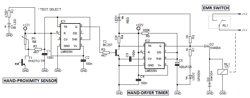
IC1 configured as medium-power inverting current driver, and IC2 as
monostable multi-vibrator. When infrared light (IR) from the infrared
light emitting diode (IR LED) falls on the phototransistor (T1), by
reflection, output of IC1 goes to high level and this will switch IC2
through the BC237 transistor (T2). As a result, the electro-magnetic
relay – EMR- (RL1) at the output of IC2 is energized to run the
hand-dryer heater unit for a prefixed time period determined by the
in-circuit values of RC timing components R5 and C5. The red LED (LED1)
is the standby mode indicator, and the green LED (LED2) is the active
mode indicator. The hand-proximity switching level can be adjusted with
the 1M potentiometer (P1). The intensity of the infrared light source
depends on the value of current-limiting resistor R2 (tested with 470R).
Both the infrared light source and the phototransistor can be mounted
side-by-side on a single panel. But, the infrared light source (IR LED)
must be isolated from the phototransistor (T1) (using a small opaque
sheet) to avoid false detection due to infrared leakage. The component
values are not especially critical. However, the coil of relay RL1 must
be have a low operating current, no more than a few dozen milliamperes.
The entire circuit should be fitted in a well-insulated enclosure, since
it is usually installed in a watery-area (rest room, bathroom, etc).


